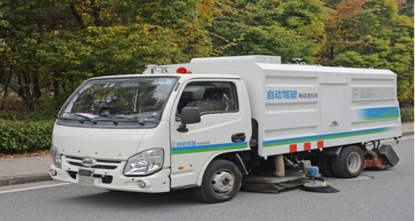
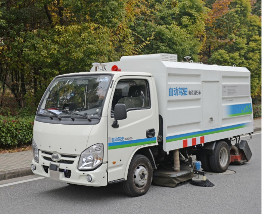
Antenna Selection for High-Precision Positioning in Autonomous Driving is a critical aspect of ensuring safe and efficient navigation. Achieving centimeter level positioning accuracy requires higher requirements for the "original observation" of navigation satellites than GNSS original positioning. This article will delve into the dependence of high-precision positioning on antennas and the factors that affect their performance.
The dependence of high-precision positioning on antennas
In order to achieve centimeter level positioning accuracy, high-precision positioning requires higher requirements for the "original observation" of navigation satellites than GNSS original positioning. This is mainly reflected in the higher requirements for satellite search, C/N0, carrier phase, Doppler value, pseudo range value, and LLI in the original observation data.
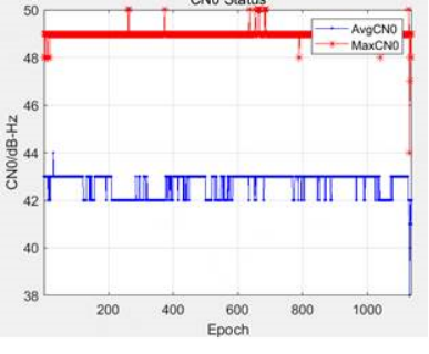
Taking the preliminary judgment standard C/N0 for the quality of satellite raw observation signals as an example, a single point positioning result can be obtained if the average C/N0 is greater than 25 dBHz. However, when the C/N0 is less than 38 dBHz, the carrier phase quality in satellite observation data can no longer meet the requirements of high-precision positioning calculation.
As a receiving and sensing source for satellite signals, the performance of positioning antennas is a necessary condition to ensure the reception of high-quality satellite raw observation data.
GNSS Antenna
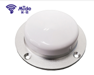
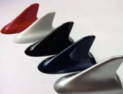
1. Antenna morphology on cars
There are two main types of GNSS antennas used in cars: single body GNSS antennas and multi in one integrated antennas. Currently, in car multi in one antennas are generally integrated with multiple combination schemes of AM/FM, 4G/5G, GNSS, wifi, and V2X. With the development of intelligent networking, the integration of terminal circuit board (Tbox V2X terminal) and antenna "smart antenna" has gradually become a trend.
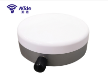
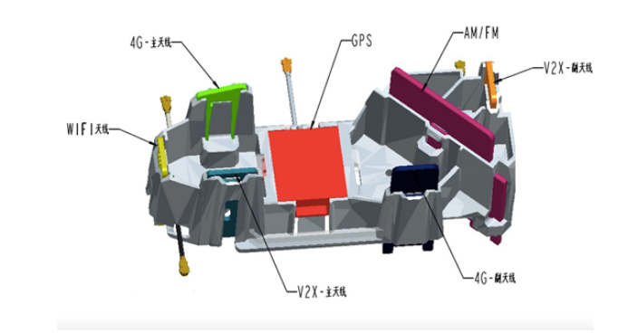
Internal structure diagram of two types of multi in one antennas:
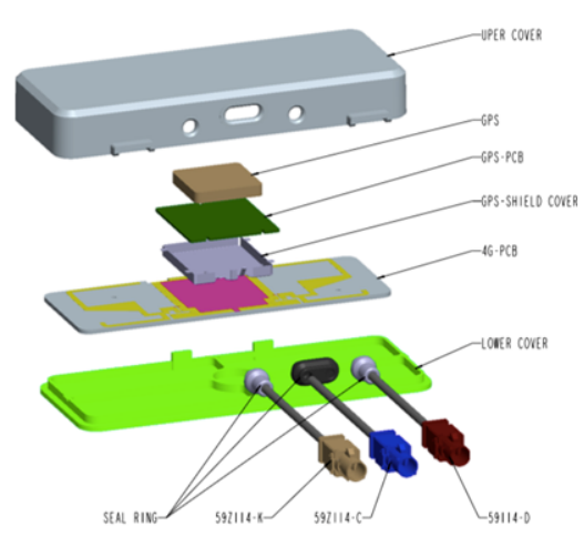
GNSS and 4G integrated box antenna disassembly diagram
2. GNSS antenna composition
The GNSS antenna for automobiles mainly consists of ceramic antennas, low noise amplifier modules, cables, and connectors.
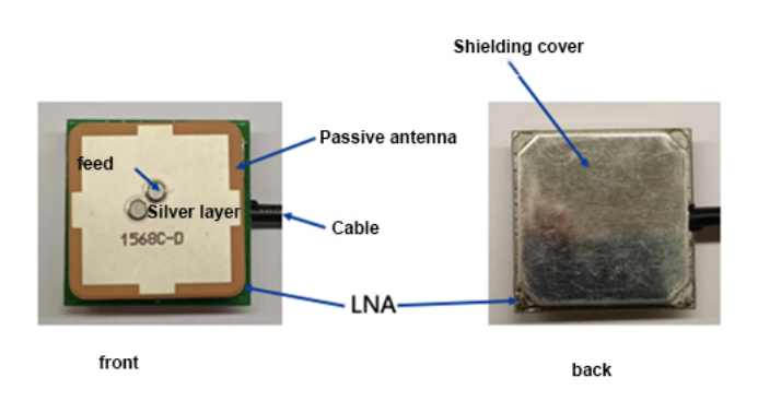
Ceramic antennas, also known as passive antennas, dielectric antennas, or PATCH, are the core technology of GNSS antennas. The signal reception capability of a GNSS antenna largely depends on the composition of its ceramic components.
The low noise signal module, also known as LNA, is the part that amplifies and filters the signal. The selection of internal components is also important, otherwise it will increase reflection loss and cause excessive noise.
The selection of cables is based on reducing losses to ensure impedance matching. The shorter the length to meet the routing requirements, the better.
3. Factors affecting the performance of GNSS antennas
1. Internal factors
size:The larger the area of the ceramic plate, the smaller the dielectric constant, the higher the resonance frequency, and the better the acceptance effect. Therefore, it is recommended to choose a large-sized ceramic antenna as much as possible in space.
Silver layer:The silver layer on the surface of a ceramic antenna can affect the resonance frequency of the antenna. The ideal GNSS ceramic chip frequency point accurately falls in the required frequency band, but the antenna frequency point is very susceptible to the influence of the surrounding environment, especially when assembled in the entire machine. The frequency point must be adjusted by adjusting the silver coating shape.
Feed point:The ceramic antenna collects resonance signals through feed points and sends them to the backend. Due to antenna impedance matching, the feed point is generally not in the center of the antenna, but slightly adjusted in the XY direction. This impedance matching method is simple and does not increase cost. Moving only in the single axis direction is called a single biased antenna, and moving on both axes is called a double biased antenna. At present, high-precision antennas generally use multi feed points to enhance phase centers, and develop from single feed to double feed and quad feed.
Four important parameters:Gain, VSWR, Noise figure, and Axial ratio. Among them, special emphasis is placed on the shaft ratio, which is an important indicator to measure the difference in signal gain of the entire machine in different directions. Due to the random distribution of satellites in the hemisphere sky, it is crucial to ensure that the antenna has similar sensitivity in all directions. The axial ratio is affected by antenna performance, external structure, internal circuit of the entire machine, and EMI.
2. External interference
The external factors that affect antenna performance mainly include:
Housing or radome:The distance between the antenna shell or radome and the antenna can affect the change in gain curvature. Generally, low dielectric constant materials should be used as much as possible for the antenna shell or radome, such as avoiding the use of coatings or paint layers with metal components on the shell;
Other antenna interference:In automotive applications, GNSS antennas are usually assembled with other antennas to form a multi in one integrated antenna. The GNSS antenna must be above all metal components, and appropriate protective and shielding measures must be taken to reduce multipath effects and prevent signal interference. Other antennas such as FM, 4G, Wifi, V2V, etc. should be unobstructed within the reception angle of the GNSS antenna signal. Theoretically, the signal frequency bands of each antenna have significant differences, However, the interference between antennas should be confirmed through actual measurement (there are many interference situations during actual measurement). In high-precision positioning applications, the GNSS antenna has the best separation form from other antennas;
shelter from:The signal reception angle above the GNSS antenna (130 °) should avoid obstruction. For example, when installing the center console, the car's explosion-proof film will cause serious obstruction to the signal, and the roof will also provide some obstruction to the antenna's signal reception;
EMI interference:The GNSS antenna, including transmission lines, should be as far away as possible from CPU, SDRAM, SD card, crystal oscillator, DC/DC, high-voltage line, WiFi module, etc;
Other interferences and losses:
Power divider:Due to the electrical architecture design needs of some vehicles, multiple terminals or positioning chips with positioning functions are used. To avoid using multiple GNSS antennas, a power divider is used, which generally reduces the GNSS signal gain. In high-precision positioning applications, it is recommended to use an unbalanced power divider to maintain a low attenuation signal to the high-precision positioning GNSS chip;
GNSS signal transmission loss:Long GNSS transmission cables can also cause losses;
· Circuit board wiring coupling interference:When GNSS signals are transmitted on the board, certain losses may also occur due to interference from vias and other lines;
· Basic requirements for high-precision positioning antenna parameters
Positioning antennas are divided into single frequency, dual frequency, and multi frequency. Currently, the automotive industry mainly uses single frequency and dual frequency antennas, which can achieve "sub meter level" and "centimeter level" positioning accuracy based on enhanced positioning services.
3. Selection Summary
· Under the conditions that meet or exceed the parameter requirements of Chapter 4, the larger the size of the GNSS antenna, the better;
· The GNSS antenna has the best separation structure from other antennas;
· When the GNSS antenna must be integrated with other antennas, the GNSS antenna should be higher than other antennas as much as possible to avoid obstruction;
· When GNSS antenna and other antennas must be integrated, shielding and isolation should be carried out between GNSS antenna and other antennas or circuit boards;
· When a power divider is necessary in the scheme, it is recommended to use a non balanced method to ensure that a high gain GNSS signal is sent to the high-precision positioning GNSS chip;
· The shorter the wiring between GNSS signals and GNSS chips, the better in theory. However, if the two are too close, EMI interference may occur and shielding and isolation are required;
·Avoid through holes and wrapping when routing GNSS signals on the board;
Testing requirements
1. Darkroom testing
The antenna darkroom test should be conducted on both active and passive components, and the parameters in Chapter 4 above should be tested in different bands to ensure the parameter requirements.
· field test
1. static state
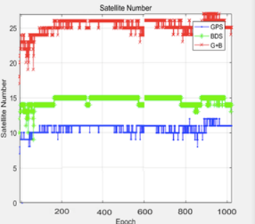
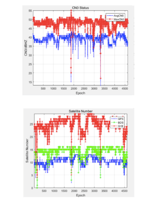
Using adaptive positioning terminals (using mass-produced matching terminals or test boards provided by terminal positioning chip manufacturers), select an open testing scenario for static positioning>20min, and calculate the original observations of each epoch positioning. The average C/N0>40 dBHz, the maximum C/N0>50 dBHz, the average number of single frequency star searches>22, and the average number of dual frequency star searches>32.
Trends
Using adaptive positioning terminals (using mass-produced matching terminals or test boards provided by terminal positioning chip manufacturers), select an open testing route for dynamic testing>30min, and calculate the original observations of each epoch positioning. The average C/N0>40dBHz, the maximum C/N0>50 dBHz, the average number of single frequency star searches>22, and the average number of dual frequency star searches>32.
1. High precision positioning test
Based on the above tests, after passing the basic tests of antenna parameters and internal and external fields, Qianxun can support the use of customer solution terminals or development boards to measure the positioning accuracy that can be achieved in conjunction with Qianxun high-precision positioning services, and further evaluate antenna performance.
The earlier the test is, the better. It is recommended that customers receive antenna samples and provide them to Qianxun for testing in advance along with the above darkroom testing and basic dynamic and static testing reports.
2. Installation guidance
1. Recommended installation location
To meet the requirements of high-precision positioning for satellite original observation, it is recommended to install the car GNSS antenna on the top of the vehicle without any self blocking position.
2. Installation precautions
· The installation position of the antenna should be at least 30cm away from other controllers in the car. When adopting an integrated antenna and terminal solution, the antenna should be effectively shielded and isolated from the terminal circuit board through electromagnetic shielding;
· The GNSS cable should be routed as short as possible in the car and as straight as possible. Excess (too long) cables should not be wrapped around;
· There is no high-voltage cable within 30cm of antenna installation and wiring;
· There is no other obstruction within the range of 65 ° above the antenna from the full circumference height angle to the zenith;
In conclusion
Selecting the right antenna for high-precision positioning in autonomous driving is crucial. The GNSS antenna's size, separation from other antennas, shielding and isolation measures, and wiring length all influence its performance. Testing and installation guidance are also essential to ensure optimal performance. With the right antenna selection and implementation, the technology can enable safe and reliable autonomous driving.