News
Site Editor
 Site
https://mide-act.usa72.wondercdn.com/uploads/image/635cdcc32f0fa.png
When installing your GNSS antenna, select a site at which the antenna will not become buried in drifting or accumulated snow. It should not be covered by foliage or placed in a position where it could become obstructed in any way. Whenever possible, avoid placing the GNSS antenna in close proximity to broadcast antennas or high-power transmitters.
Site
https://mide-act.usa72.wondercdn.com/uploads/image/635cdcc32f0fa.png
When installing your GNSS antenna, select a site at which the antenna will not become buried in drifting or accumulated snow. It should not be covered by foliage or placed in a position where it could become obstructed in any way. Whenever possible, avoid placing the GNSS antenna in close proximity to broadcast antennas or high-power transmitters.
Outdoor GNSS Antenna Installation Considerations
Views: 468
Author: Site Editor
Publish Time: 2023-03-21
Origin: Site
Many Mide timing and synchronization products utilize an embedded GNSS (Global Navigation Satellite Systems) receiver as a primary reference. Typical installations utilize an outdoor active GNSS antenna to collect and transmit GNSS satellite radio signals to the receiver via an RF cable. This technical note describes the main considerations for a successful outdoor GNSS antenna installation for a timing application:
-
Locating the antenna
-
Connecting to the antenna
-
Using ancillary products
-
Evaluating signal attenuation to validate cable length
-
Using signals in addition to GPS L1
Locating the GNSS Antenna
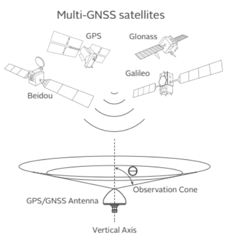
The GNSS antenna must have a direct view of GNSS satellites with an unobstructed line of sight to the sky. Rooftops that are clear of other structures or geographic features overhead, with views to the horizon, generally make good installation locations. Such a clear view allows the antenna to track the maximum number of satellites throughout the day. Installations with obstructed views may experience reduced reception quality and may not be able to simultaneously track the maximum number of satellites. An observation angle of 70° from the vertical axis (20° above the horizon) usually offers good performance. Contact Mide if your antenna location’s view of the sky is restricted for mitigating approaches.
When installing your GNSS antenna, select a site at which the antenna will not become buried in drifting or accumulated snow. It should not be covered by foliage or placed in a position where it could become obstructed in any way. Whenever possible, avoid placing the GNSS antenna in close proximity to broadcast antennas or high-power transmitters.
Connecting to the Antenna
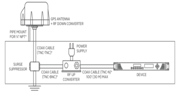
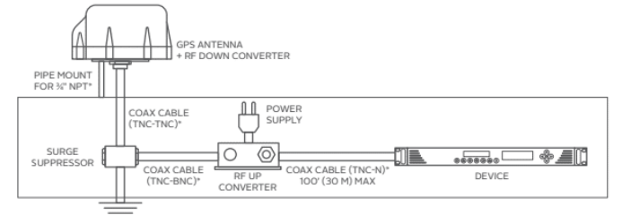
A coaxial cable transmits GNSS signals from the antenna to timing receiver. It also conducts 5 volts from the receiver to power the antenna and other elements of the antenna system if necessary. The choice of cable is on the basis of attenuation characteristics, weathering ability, temperature rating, and UV resistance. Type N female connectors are used on the antenna and any other element in the antenna cable system, therefore male connectors terminate cables. While Type N female connectors are used on many receivers, smaller form factor products can require the use of alternative connectors. Therefore a different connector may need to terminate the cable to the receiver or an adapter can be used. The application of weather proofing sealant or tape is a good idea for all outdoor connections.
Do not allow the antenna cable to be placed in standing water, as water may permeate through the coax jacket over time. On flat roof installations, the cable may be suspended by cable hangers or placed in sealed conduit. GNSS antenna cable can be installed through a conduit either by itself or with other cables. The conduit dimensions must be large enough to accommodate the “N” type connectors, which have a diameter of about 0.8 inches (20 mm), and the GNSS cable itself, which has a diameter of about 0.4 inches (10 mm) for LMR400 equivalent. Using a conduit that is too small or whose bend radius is too tight will prove difficult during installation (and may actually damage the cable). The maximum bend radius of the antenna cable can be as little as 1 inch (25 mm) and as large as 4 inch (100 mm) depending on the type of cable.
Using Ancillary Products
Several items are available to improve the functionality and reliability of a GNSS antenna system. You can leverage the installation of a single GNSS antenna across several GNSS devices by the use of an RF splitter. A surge suppressor is strongly recommended to protect indoor equipment against lightning damage. Install a surge protector and properly connect it to earth ground at the point where the antenna cable enters the building. It is best to calculate cable distances from the antenna to the surge suppressor and surge suppressor to receiver so two connectorized cables can be ordered at the proper length. This saves time and eliminates the risks of splicing cable and installing connectors in the field.
For installations that require a long cable run, an inline amplifier can be used to ensure signal levels at the receiver. The amplifier should be placed at a point where the antenna gain has been reduced to 10 db. It should also be placed a minimum of 5 ft (1.5 m) from the surge suppressor to protect it from lightning damage.
All ancillary items used in the GNSS antenna cable system are required to pass 5 volts from the receiver to the antenna (nominally 27 ma). This power can be used for other items in the system.
Evaluating Signal Attenuation to Validate Cable Length
The question of maximum cable length is dependent on the sum of the gain (and losses) of all the items in the GNSS antenna system and the tolerance for minimum gain required for reliable operation of the receiver. A good way to evaluate these considerations is the following equation:
Antenna Gain − Cable Loss − 1 db/Surge Suppressor − 0.5 db/Connector + 20 db/Inline Amplifier ≥ Minimum Receiver Gain
GNSS Signals, Beyond GNSS L1
GNSS antenna systems may need to accommodate a variety of signals as required by the receiver capability. For instance, authorized users of SAASM receivers utilize signals at different frequencies (L1 and L2). While there had been limited alternatives in commercial applications, the proliferation of Global Navigation Satellite Systems (GNSS) now offer the
benefit of redundancy by receiving signals from different systems and at different frequencies.
A common application today is to combine:
-
GPS L1 (1575.42 MHz)
-
Galileo E1 (1575.42 MHz)
-
GLONASS L1 (1602.0 MHz)
-
BeiDou B1 (1561.1 MHz)
-
QZSS L1 (1575.42 MHz)
-
optional SAASM: GPS L1 & L2 (1227.6 MHz)
Mide-provided antenna systems support combinations of L1 and L2 or GNSS/GLONASS L1. Other antenna systems should be checked for compatibility with the required range of GNSS signals.
*Kit includes:
-
Fiber optic transmitter (E) with power supply (F)
-
Fiber optic receiver (H) with power supply (G)
-
Type N to SMA adapter for transmitter and SMA to N adapter for receiver
RF Converter Kits
-
GPS antenna and cable system kit extends distance to 1,500 ft (450 m)
Looking for a reliable and professional manufacturer to provide high-precision positioning solutions worldwide?
Look no further than Mide - the leading OEM in GNSS antenna, receivers, and solutions.
Our products have been widely adopted in various industries such as land surveying, unmanned systems, deformation monitoring, digital construction, navigation, smart city, and automatic driving. With our constant innovation and breakthroughs in the GNSS industry, we are always exploring new applications of GNSS technology.
Choose Mide for robust and reliable whole GNSS industry products and high-precision solutions that will transform your working methods and boost efficiency. Trust us to deliver top-quality products and services that meet your exact needs.