What is antenna pattern?
The directivity of an antenna refers to its ability to radiate electromagnetic waves in a certain direction. For a receiving antenna, directivity means that the antenna has different receiving capabilities for electromagnetic waves transmitted from different directions. The directivity of an antenna is usually represented by a pattern.
Radiation pattern of antenna : If the radiation intensity of antenna in all directions is represented by vectors starting from the origin, the surface formed by connecting all vector endpoints is the antenna pattern. That is, the pattern is a function graph of antenna radiation parameters changing with space coordinates. The radiation parameters can be the radiation power flux density, field strength, phase, polarization, etc. of the antenna. Usually, we pay more attention to the power pattern or the field intensity pattern.
Features of antenna pattern
The radiation characteristics of the antenna can be described by three-dimensional and two-dimensional patterns. The three-dimensional pattern can be divided into spherical three-dimensional pattern and rectangular three-dimensional pattern; The two-dimensional pattern is obtained by taking a certain section from its three-dimensional pattern, and is divided into polar coordinate pattern and rectangular coordinate pattern.
Spherical coordinate system
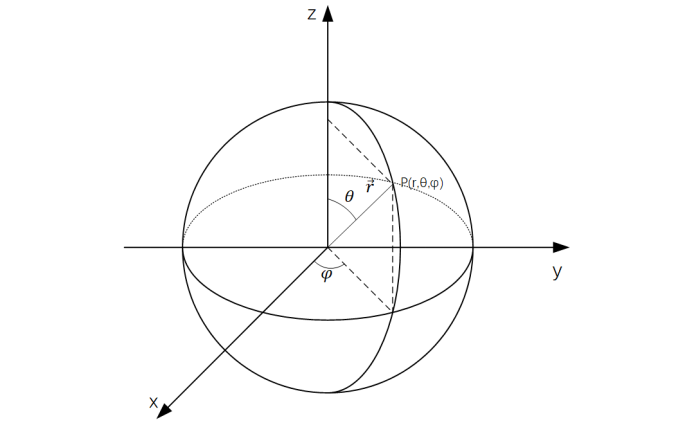
In mathematics, spherical coordinate system is a three-dimensional orthogonal coordinate system that uses spherical coordinates to represent the position of a point P in three-dimensional space. The following figure shows the geometric meaning of spherical coordinates: the distance r from the origin to point P, and the included angle between the line from the origin to point P and the positive axis of z axis Θ. The included angle between the projection line of point P on xy plane and the positive axis of x-axis φ。
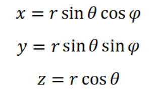
Transformation between spherical coordinate system and rectangular coordinate system

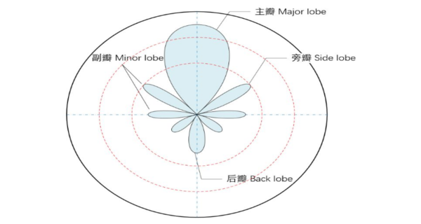
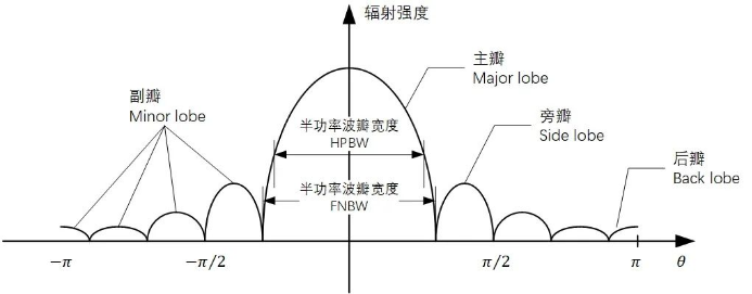
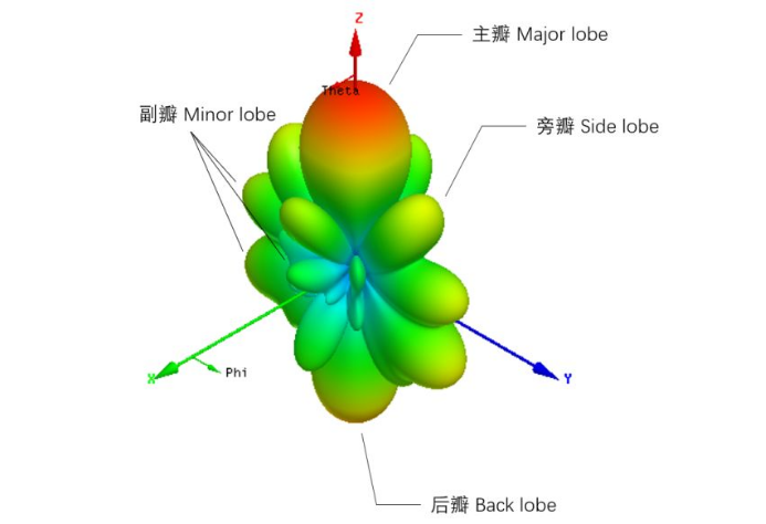
In the pattern (also known as the lobe pattern), the radiation lobe containing the required maximum radiation direction is called the antenna main lobe, also known as the antenna beam. The lobe outside the main lobe is called the side lobe or side lobe or side lobe, and the side lobe in the opposite direction of the main lobe is called the posterior lobe or tail lobe.

The pattern is a far field concept. The far field is the distance between the point of the radiation field under investigation and the antenna, which is very large compared with the wavelength. At this time, the shape of the pattern is independent of the distance between the radiation field point and the antenna, but only related to the spatial angle.
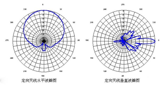
Since the antenna pattern is a spatial angle( Θ,φ) In spherical coordinate system, the function of is presented in 3D form. Therefore, sometimes we focus on the antenna pattern of two main planes to understand the relationship radiation performance of the antenna.
In the online antenna, due to the great influence of the ground, the vertical plane and the horizontal plane are used as the main plane.
In the plane antenna, the E plane and H plane are used as the two main planes:
◈E plane (also called electric plane) refers to the plane where the maximum radiation direction and electric field vector of the antenna are located.
◈ H plane (also called magnetic plane) refers to the plane where the maximum radiation direction of the antenna and the magnetic field vector are located.
◈ The E and H planes are orthogonal to each other.
Different antenna patterns are required for different purposes. For example:
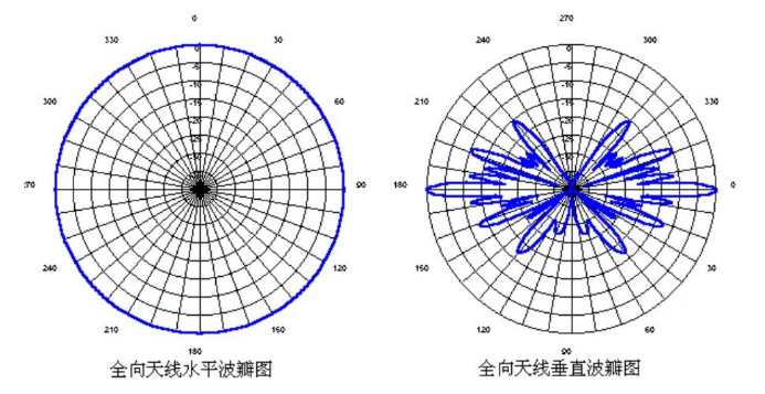
• The radio and television transmitting antenna, mobile communication base station antenna, etc. shall be omnidirectional in the horizontal plane and have certain directivity in the vertical plane to improve the antenna gain.
• For antennas used for microwave relay communication, remote radar, radio astronomy, satellite reception, etc., pencil beam pattern is required.
• For search radar and guard radar antennas, the antenna pattern is required to be sector beam.
Gain
Directionality coefficient:
A parameter used to characterize the concentration of antenna radiation energy. Under the condition of the same radiation power Pr, the ratio of the radiation intensity of an antenna in a given direction to the radiation intensity of an ideal point source antenna in the same direction. In general, the directivity coefficient refers to the directivity coefficient of the maximum radiation direction.
Antenna gain:
Under the condition of the same input power Pin, the ratio of the power density of the signal generated by the actual antenna and the ideal point source at the same point in space. It quantitatively describes the extent to which an antenna concentrates and radiates the input power, and is used to measure the antenna's ability to send and receive signals in a specific direction.
It is noted that the definition of gain is different from the definition of the directivity coefficient. The directivity coefficient is defined by the radiated power, without considering the energy conversion efficiency of the antenna; Gain is defined by the input power of the antenna.
The gain is obviously closely related to the antenna pattern. The narrower the main lobe of the pattern (the more concentrated the energy radiation), the smaller the side lobe (the less energy dispersion), and the higher the gain. Polar plots are mostly used to characterize the pattern with medium and low gain, that is, the pattern with fat lobe; Cartesian coordinates are often used to plot the pattern of high gain (narrow beam, low sidelobe) antennas
Unit dB dBi dBd
The measurement unit of antenna gain is decibel (dB). Decibel is a concept used to represent the proportion of two values of the same unit. It is the logarithmization of multiple values, which can easily and intuitively reflect the size relationship of two values.
The antenna gain is relative to the reference antenna. Generally, the radiation intensity of omnidirectional antenna or half-wave dipole antenna with the same power input in a certain direction is taken as the reference value. The reference time of the omnidirectional antenna is recorded as dBi (i-isotropic), and the reference time of half wave symmetric dipole antenna is recorded as dBd (d-dipole)
Common gain
Whiplash antenna 6~9dBi, Yagi antenna 15-17dBi for base station, parabolic directional antenna can easily achieve 24dBi, and microstrip patch antenna gain is generally 5~8dBi
Approximate Calculation Formula of Parabolic Antenna:
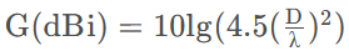
D is the diameter of the paraboloid, λ Is the central working wavelength.
Approximate formula for vertical omnidirectional antenna:
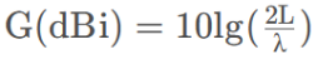
L is the antenna length, λ Is the central working wavelength.
The gain of the antenna is generated by the superposition of the dipoles. The higher the gain, the longer the antenna length.
Want to learn more about antenna pattern?
Mide is a professional manufacturer(OEM) that develops and manufactures GNSS antenna, Receivers and Solutions for high-precision positioning applications worldwide. If you want to learn more about antenna pattern, please kindly contact us.