The Internet of Things project relies on a wireless connection to connect devices, but the best connection type and antenna technology depend on relevant applications.
Wi-Fi may be a good choice for access points, portable devices or IP cameras, while industrial applications such as remote monitoring, smart meters, smart buildings, smart cities, manufacturing automation, smart agriculture and tracking are more likely to use LP-WAN networks, such as NB-IoT, LoRa, SigFox, ISM 791-960MHz or cellular networks. Each type of network has a variety of embedded antennas.
The selection for the antenna
The antenna you select should be neatly suitable for PCB layout and stacking. In addition, it must operate within the required range, operate without interference, and use a reasonable power level. When the design enters the test stage, all these performance factors will be verified, but the smart antenna selection and design meeting its requirements will make the design have a good start.
At first glance, a smaller antenna may look promising, but there is more to consider. The topology of the antenna determines its efficiency, bandwidth, radiation pattern and gain, so the smallest antenna may not be the best choice.
There are many design factors to be considered, including the proximity of the antenna to other components, the position of the antenna on the board, the requirements of the antenna ground plane and the interference level in the equipment use environment.
Chip or surface mount design (SMD) antennas have become very popular in small devices. Here, we review the main types of SMD-embedded antennas.
Surface Mount Device (SMD) antenna
The SMD antenna needs a ground plane - a certain amount of space for the antenna to resonate - located below or near the antenna. This means that the antenna package must have no other components that may interfere with the antenna radiation, and all layers on the PCB should have similar gaps.
Only antenna pads and connections to feed and ground exist in the clearance area (Figure 1). The grounding plane requirements of each antenna will be described in the manufacturer's datasheet.
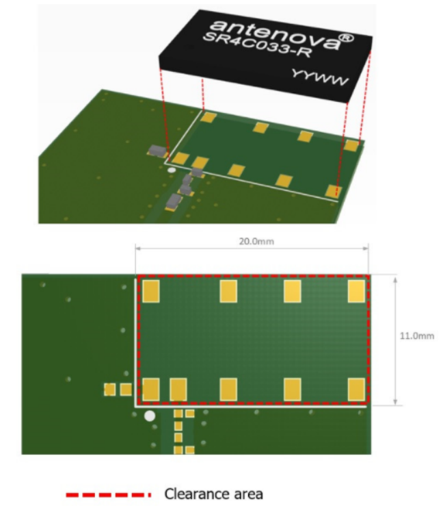
Figure 1. This kind of antenna, LP-WAN's Latona chip antenna needs a gap of 20.0 x 11.0 mm, which is the same size as the antenna.
Tracking antenna
Tracking antenna was once an obvious choice. They are relatively cheap and can be replicated quickly and on a large scale.
However, they occupy ten times more space on the circuit board than modern chip antennas. Because they are pure two-dimensional, they cannot provide the same space-saving functions as planar inverted F antennas (PIFA), chips and even patches. In practice, they may be difficult to adjust, because small changes in circuit board materials or component layout will affect their performance, and they are not always optimized for your equipment.
Ceramic patch antenna
Ceramic patch antennas are very popular in positioning applications and can work well in vehicles, but their popularity has declined due to various reasons.
First of all, they have a strong directionality and must point directly at the sky to operate effectively. Small ceramic patch antennas may be expensive, but their performance will vary due to the shortage of ceramic materials that can be used to transmit and receive RF energy.
Smaller patch antennas often only support a narrow frequency band, so other types of antennas are preferred when wider frequencies are required.
PIFA antennas
PIFA has become the de facto wireless solution. They are now ubiquitous in handheld devices, wearable devices and small Internet of Things devices, mainly because they can provide a high level of performance and small size, but also because they are widely available and cheap. They resonate at 1/4 wavelength and produce good SAR characteristics.
All these make them convenient choices for designers. They are easy to integrate, and circuit matching only involves a simple matching circuit. Another advantage: they can be placed on the top of the PCB ground plane to allow the components to be placed under the antenna. PIFA is the most popular antenna topology at present, because it is compact and can provide a high level of performance.
Electrically small antenna
ESA or an electric small antenna is much shorter than its specified wavelength. Some antennas work on 1/4 or 1/2 of the ground plane, while ESA can be as small as 1/10 of the wavelength.
Some of the first antennas in the world use this topology, and their performance has recently been significantly improved in terms of gain, bandwidth and field pattern. These antennas may be small and may be less than 20 mm. They are relatively unaffected by proximity and detuning, and can use a technology called beam control to expand their system capacity relatively easily.
Magnetic loop antenna
Finally, there is a magnetic ring antenna, which is coupled with the magnetic wave in the area near the antenna. They work perfectly in ultra-small devices that need to achieve high performance in a compact form factor. They have the ability to resist detuning, and are the ideal choice for wearable and handheld devices with very valuable PCB space and critical performance.
SMD is not the only solution for embedded wireless; There are other antenna topologies that may be useful for some IoT and embedded designs.
There are flexible and external antennas, both of which have advantages. The flexible antenna is not directly located on the PCB and does not need a ground plane. The external antenna is located outside the equipment, which can be well-matched with various grounding plane dimensions and can operate effectively in free space, thus simplifying antenna integration.
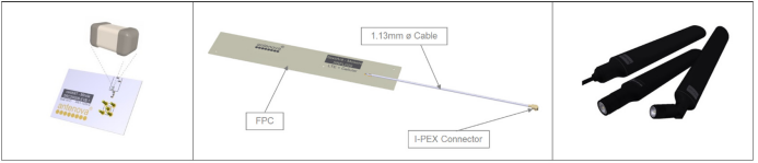
Figure 2. SMD, FPC and terminal antenna
Flexible antenna
If there is not much space in the equipment, flexible antenna (FPC) may be a good choice. The FPC does not need to be placed on the actual PCB - it is connected to the system through its own integrated I-PEX cable.
FPC does not need ground plane to radiate, so it can be plugged into the equipment shell. This helps to save space on the PCB, but FPC antenna integration needs to be careful, because the cable will actually become part of the antenna during radiation.
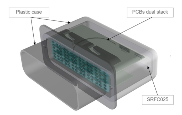
Figure 3 The SRFC025 flexible antenna placed in the tracking equipment housing is connected to the circuit board through its cable and I-PEX connector.
Terminal antenna
When the application needs mission-critical wireless performance, the terminal antenna may provide the opportunity to obtain the highest performance level - especially in an environment with other RF noise. These antennas are much larger and placed outside the equipment.
They can achieve excellent performance in free space without any adjustment or matching in the device.
Circuit board size and layout: space saving
The size and layout of PCB design may determine your antenna selection. Space is always valuable, so a compact and low-profile antenna is usually a good choice
Please remember that the antenna should be kept away from other "noisy" components, such as batteries, motors and designed metal parts, which may cause interference and affect the wireless performance of the device. If the shell of the equipment is made of metal, it may cause problems, so plastic is usually a safer choice
Internet of Things environment
Finally, a good wireless design should be created to run in the environment where it is used.
IOT solutions often appear in commercial and industrial environments. There are IoT applications in factory automation, vehicle and container tracking and intelligent building measurement solutions. However, these may not be good environments for RF. When there are metal objects, or motors, or other wireless devices, or even people nearby, the wireless performance may be affected.
The test design in the anechoic chamber will show the performance of the equipment in the perfect environment, but each prototype should also be tested in its real working environment. Testing is the first step to achieving work design and obtaining regulatory approval.
Want to know more about antenna for IOT applications?
Mide is a professional manufacturer(OEM) that develops and manufactures GNSS antenna, Receivers and Solutions for high-precision positioning applications worldwide.
The products are widely used in land surveying, unmanned systems , deformation monitoring , digital construction, navigation, smart city, automatic driving and so on. If you want to know more about antenna for IOT application, kindly contact us today.